Vehicles
8 minutes read
Vehicles can be found in the PrefabHierarchyObject folder under the name Net[name].glb, for example NetAttackHelicopter.glb.
General process
Delete empty objects and LOD1 objects
When imported into Blender, the file looks like this : 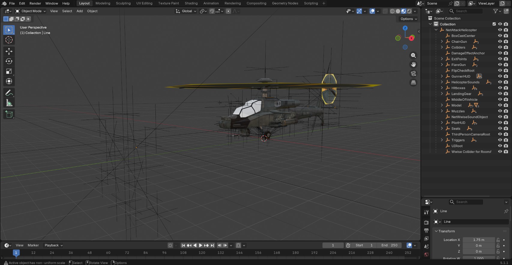 Before using it, it is good to clean up the file and delete the useless objects.
The general process is the following : first, press A and Alt + P, then select Clear and Keep Transformation.
To delete all empties, click on the filter icon on the top right corner of the outliner, unpick meshes and collections, then press A and X to delete all empties. 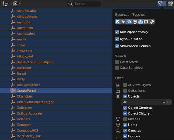
In the search bar, search for LOD1 objects and delete them. They correspond to the lower level of detail and will not be used here.
Apply materials
You can then import materials based on the methods proposed in the materials section. Transparent materials like the glass in the helicopter cockpit are not imported, so I used this material setup : 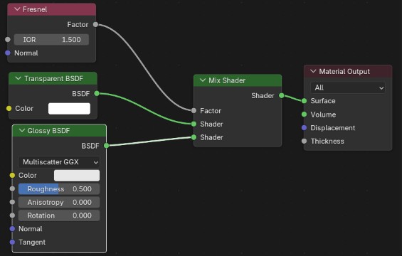
I also changed the render method in the material settings for a better look : Material > Settings > Surface > Render method > Blended
Rig the vehicle
The rig system will be detailed for each type of vehicle. Some, like the Jetski and the Zodiac, don’t event need a rig because of their simplicity.
The rigging process will consist in :
- Making a basic armature which supports the different moving elements ;
- Parenting the different objects to the bones, to do this :
- select the bone in Edit mode ;
- select the objects in Object mode, then select the armature ;
- press Ctrl + P and select
Boneto parent the bone ; - if the child object moves, use the option in the window appearing in the bottom left corner of the viewport to reset its position.
- Setting up widgets to make the rig more understandable ;
- Using drivers and constraints if needed, to make it easier to use the rig.
Tanks
Armature setup
The tank and the AA gun can be found in PrefabHierarchyObject as NetTank.glb and NetAAVehicle.glb. Both require the same type of rig.
The main body, threads and wheels are parented to a Root bone which will move the entire vehicle. Two other bones will control the turret and the main gun. Finally, a target bone is used to control the turret and the gun.
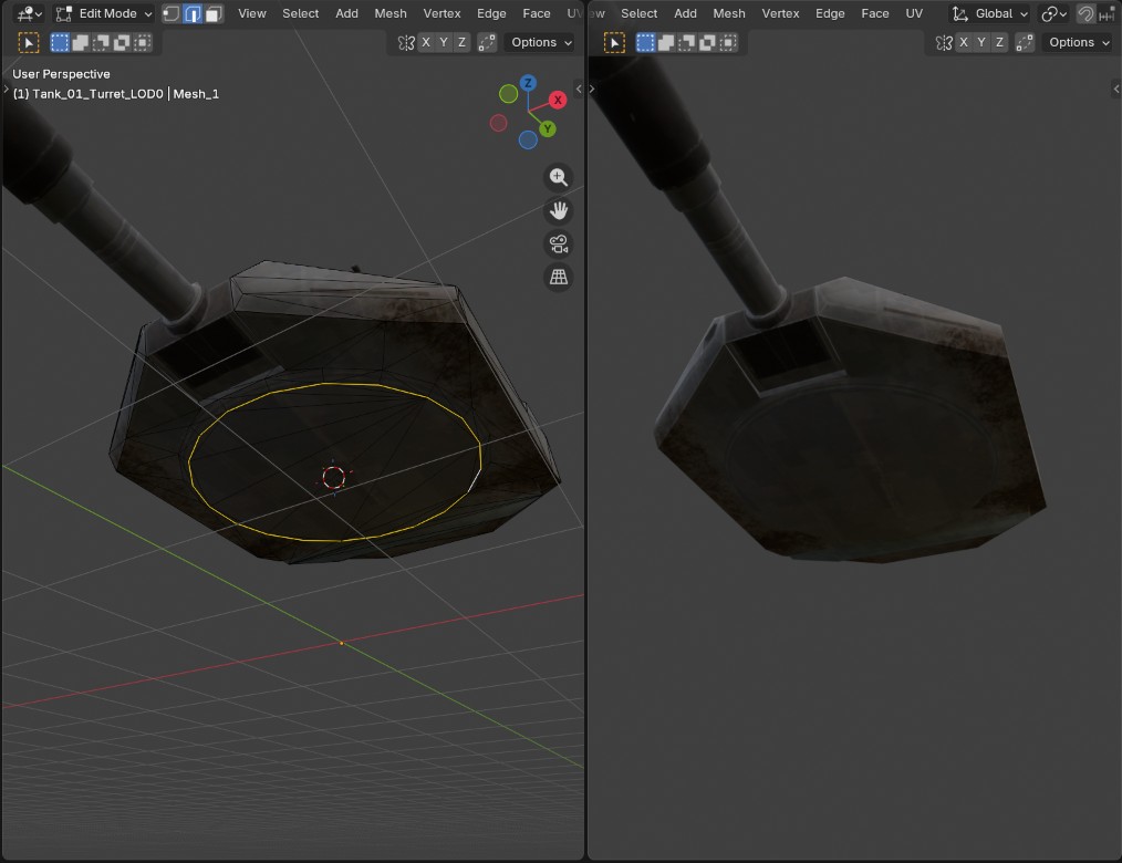
It is important that the head of the bones is located at the pivot point of the parts that will rotate. To do this (if the origin of the object is not at the pivot point), select the mesh object, go to Edit mode, then select the circular part (either its edge or its faces), and use Mesh > Snap > Cursor to selected to place the 3D cursor at the pivot point. Return to Object mode, select the armature and add a new bone. By default, it will be placed at the 3D cursor.
Constraints
To set up the constraints, make sure all of the bones are displayed and go into Pose mode. Select a bone and go to the Bone constraints tab.
Caution
Do not use the
Constraintstab, which will affect thearmatureobject and not the individual bones.
There are several types of constraints to make an object look at another : Damped track, Track to and Locked track. We will use the latter to track the target bone with a rotation on a single axis. The constraint setup is the following :
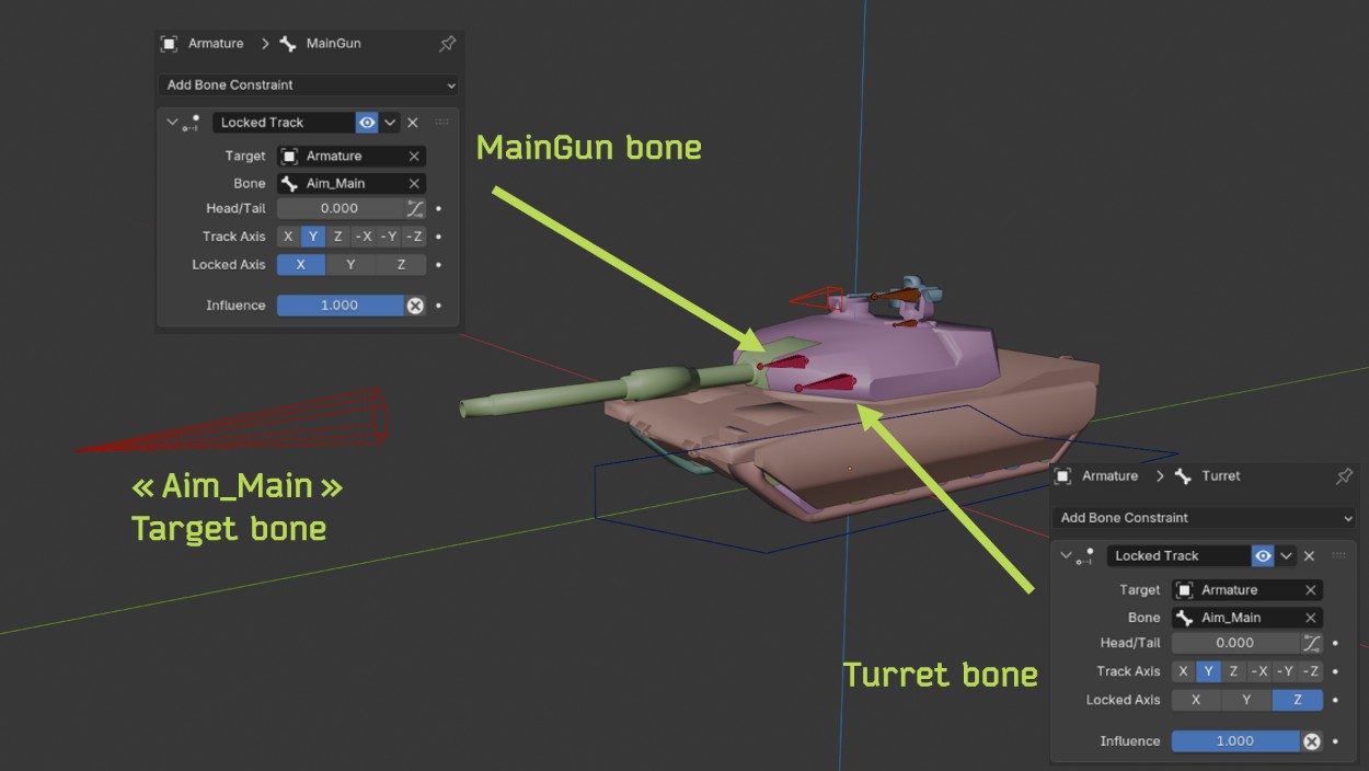
The same method can be used with the machine gun on the tank or any other vehicle.
Animating the tracks
The tank tracks are made of a single continuous object (unlike real tracks) on which a texture is applied. 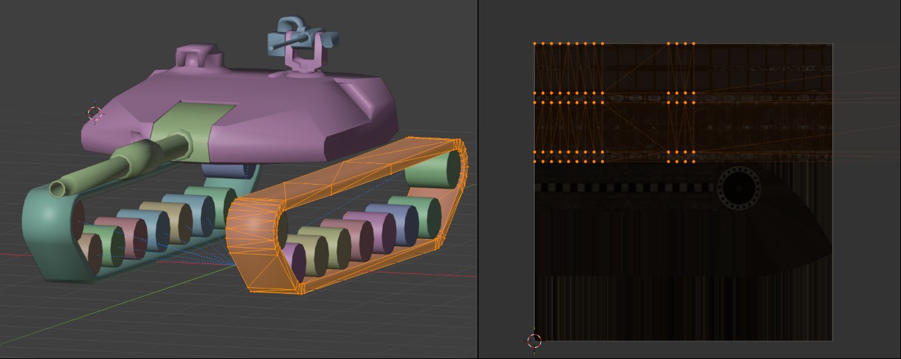
This will make the process of animating them much easier : instead of moving the actual mesh, me can simply move the texture coordinates. To do this, first duplicate the tracks material, as we will need one for the right tracks and one for the left tracks. Then, use a Texture coordinate > UV node plugged into a Mapping node connected to the textures. Right click on the Location > X parameter and select Add driver. The driver setup is the following : 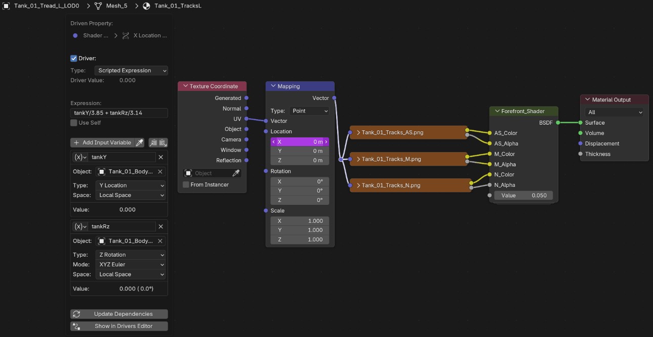
The idea is to use the tank’s own coordinates to tell the tracks how much they should move. The driver is the sum of the tank body position and of its rotation, each adjusted by a different factor to make sure the tracks don’t look like they are slipping on the ground. This way, the tracks will move if the tank is going forward and/or rotating.
I consulted tutorials but they did not explain how to adjust this factor, so I did it mostly by trial and error. I tried to calculate it based on the length of the track but the result was not as good.
Note
- The setup presented in the picture is for the left track. When the tank is turning, the tracks rotate in different directions, so the expression for the right track is tankY/3.85 - tankRz/3.14.
- In this setup I used the World Space coordinates on the Y axis, but it breaks if the tank is advancing on the X-axis ! I will fix this for the blend file release by using the Local coordinates instead.
Animating the wheels
The wheels follow a similar method, except instead of sliding a texture we will be rotating the object. To do this I followed Aryan’s tutorial, who uses a Transformation modifier (which in effect is the same as a driver).
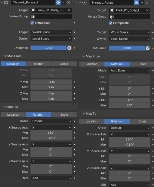
Like the threads, the parameters must be different for the right side and the left side.
Wheeled vehicles
The wheeled vehicles are NetTank.glb, NetHumvee.glb and NetAPC.glb. I used the Rigacar add-on which provides a lot of useful functionalities, like a suspension system. Documentation is avalaible on the creator’s website, however it is not maintained anymore, and you need to find a version compatible with Blender 5. I used PurpBatBoi’s fork.
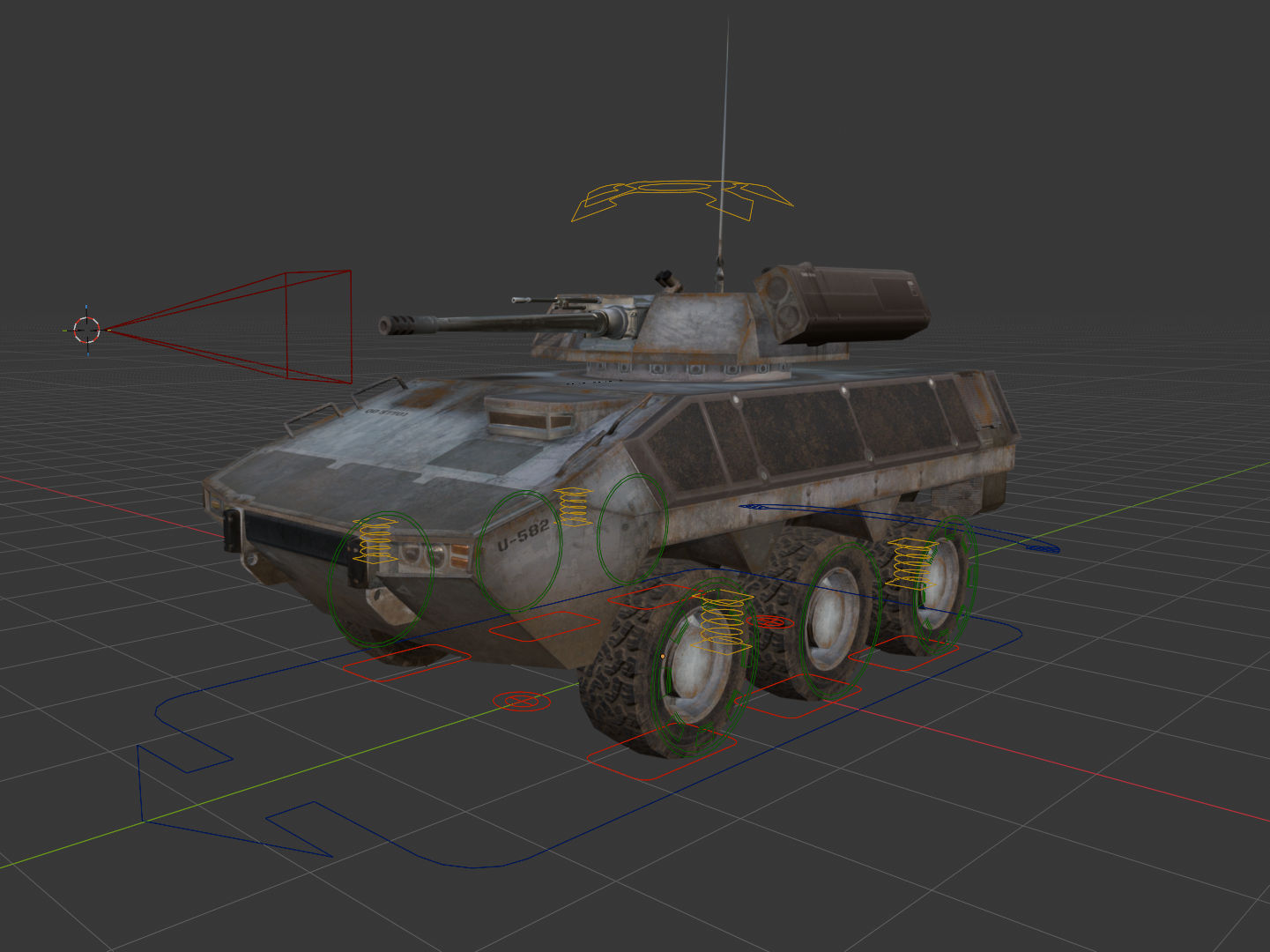
On this example I also added a few bones for the APC turret and gun, like in the tank example. For the Quad and the Humvee, I also added a Transformation constraint to make the steering wheel controlled by the steering bone.
Helicopters
Helicopters have no wheels or threads so they’re easier to work with. You only need a root bone, plus a bone for each rotor. In my rig, I also added some bones to control the rotor speed (instead of having to animate it manually) and bones to control the joysticks in the cockpit. The machine gun is setup in the same way as the tank turrets.
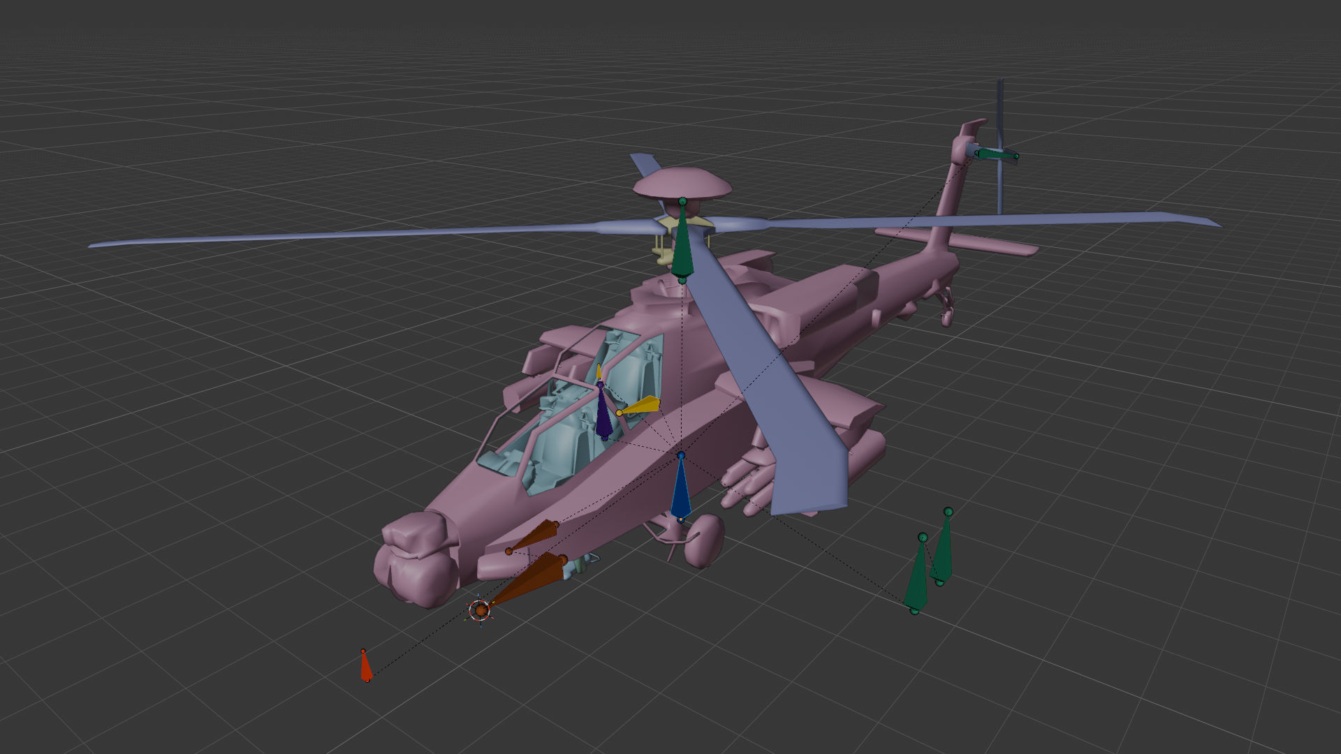
The rotation of the rotor is controlled by the following driver : 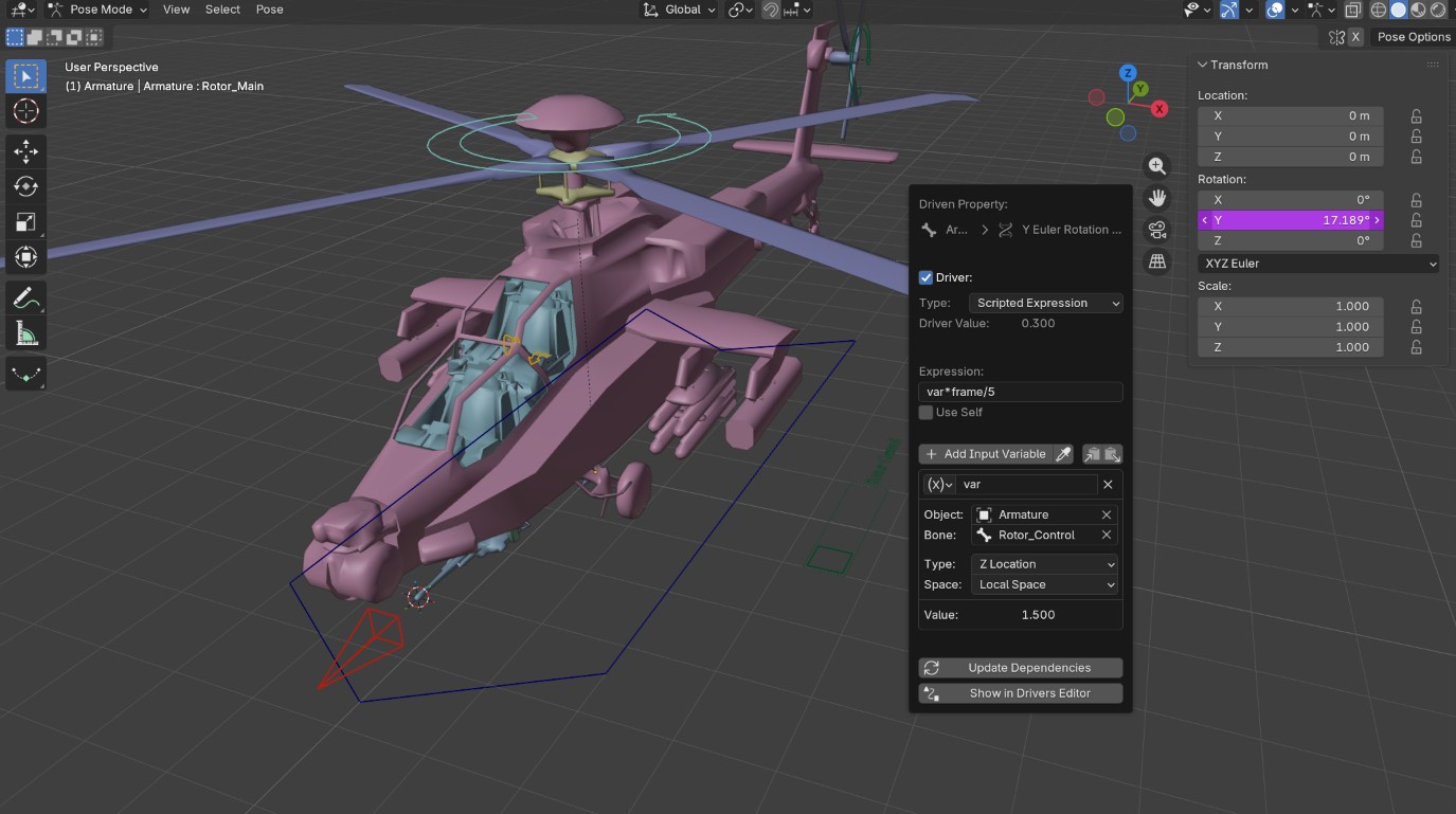 The rotor roatation will depend on the position of the Rotor_control bone (from 0 to 1.5m), on the current frame number, and on an arbitrary factor. The factor can be adjusted to set the maximum rotation speed, and its value will depend on the scene frame rate.
I used a similar method to animate the miniguns on the Littlebird.
Adding widgets
You can use any object to define the bone display in Bone > Viewport display > Custom shape. This shape can be a mesh or created with an add-on like the Bone Widget add-on.
In general it is also a good idea to hide the bones that are constrained and cannot be moved manually (like the turret and gun bones for the tanks, that are controlled by a tracking constraint).